Product Overview
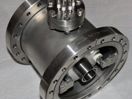
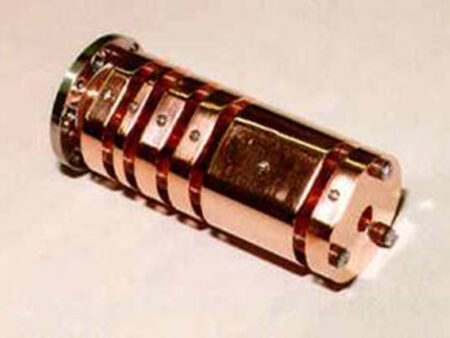
Beam Imaging Solutions presents the new model 450 ion beam decelerator for generating high current low energy ion beams. This decelerator was designed to increase low energy ion beam current by minimizing ion beam scattering with larger lens elements and also allowing for much higher initial ion beam energies before deceleration.
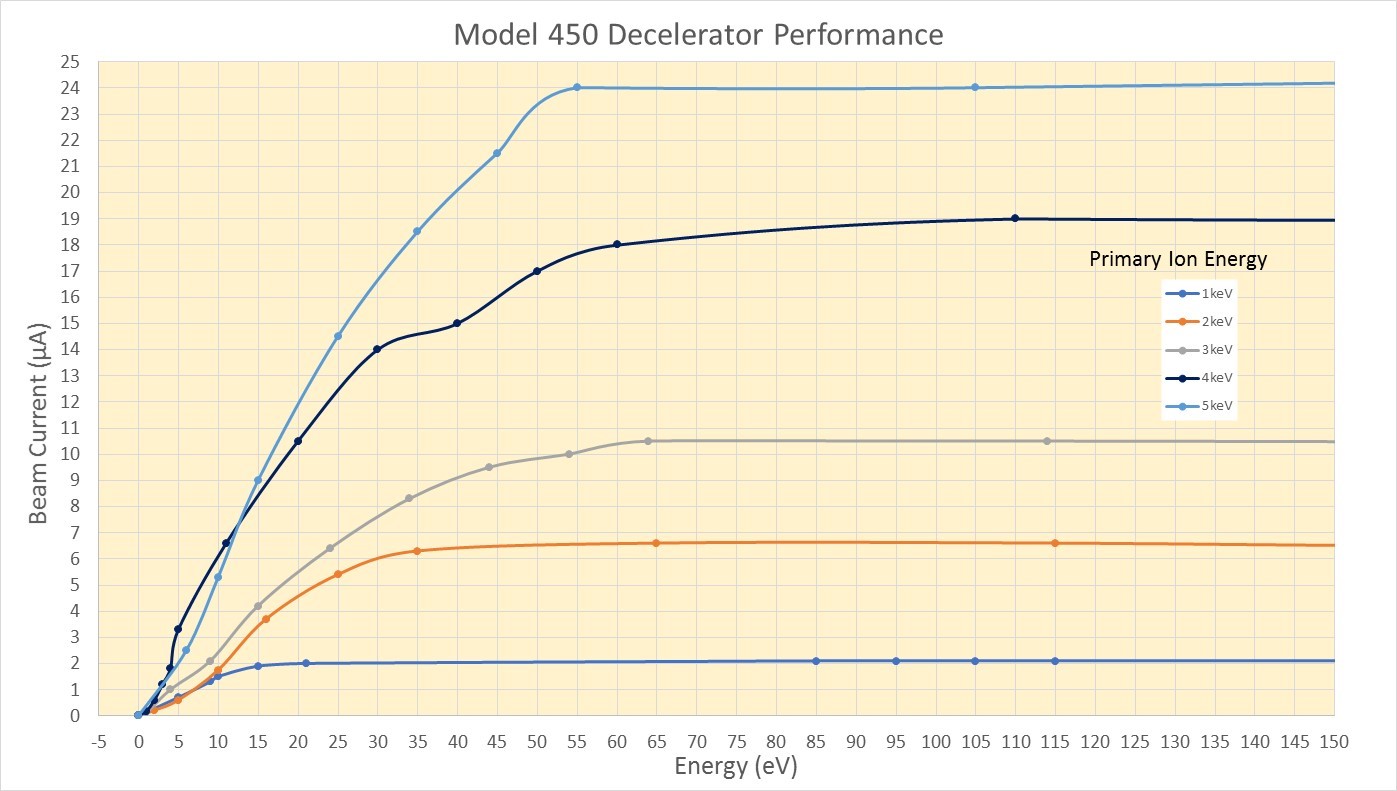
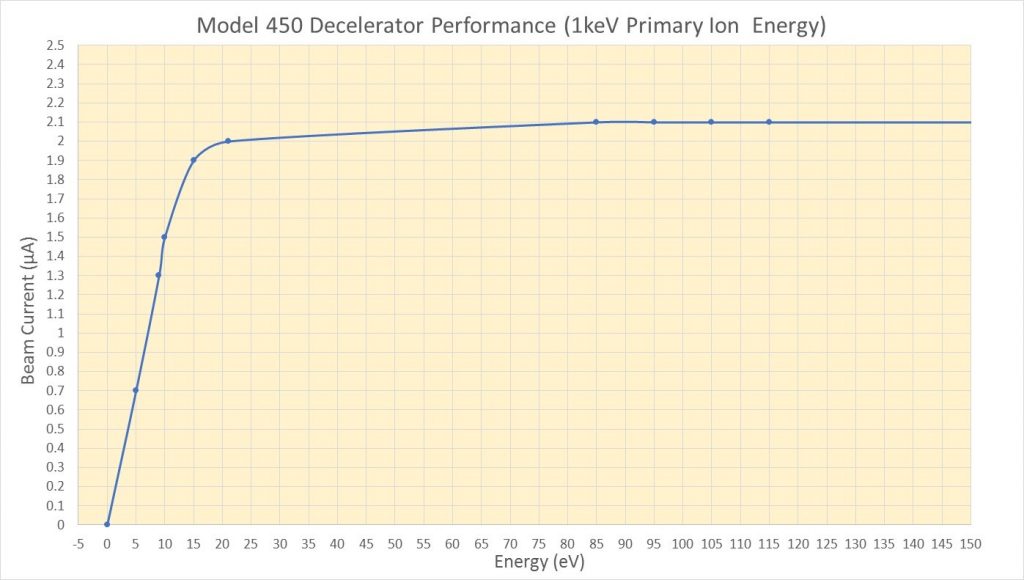
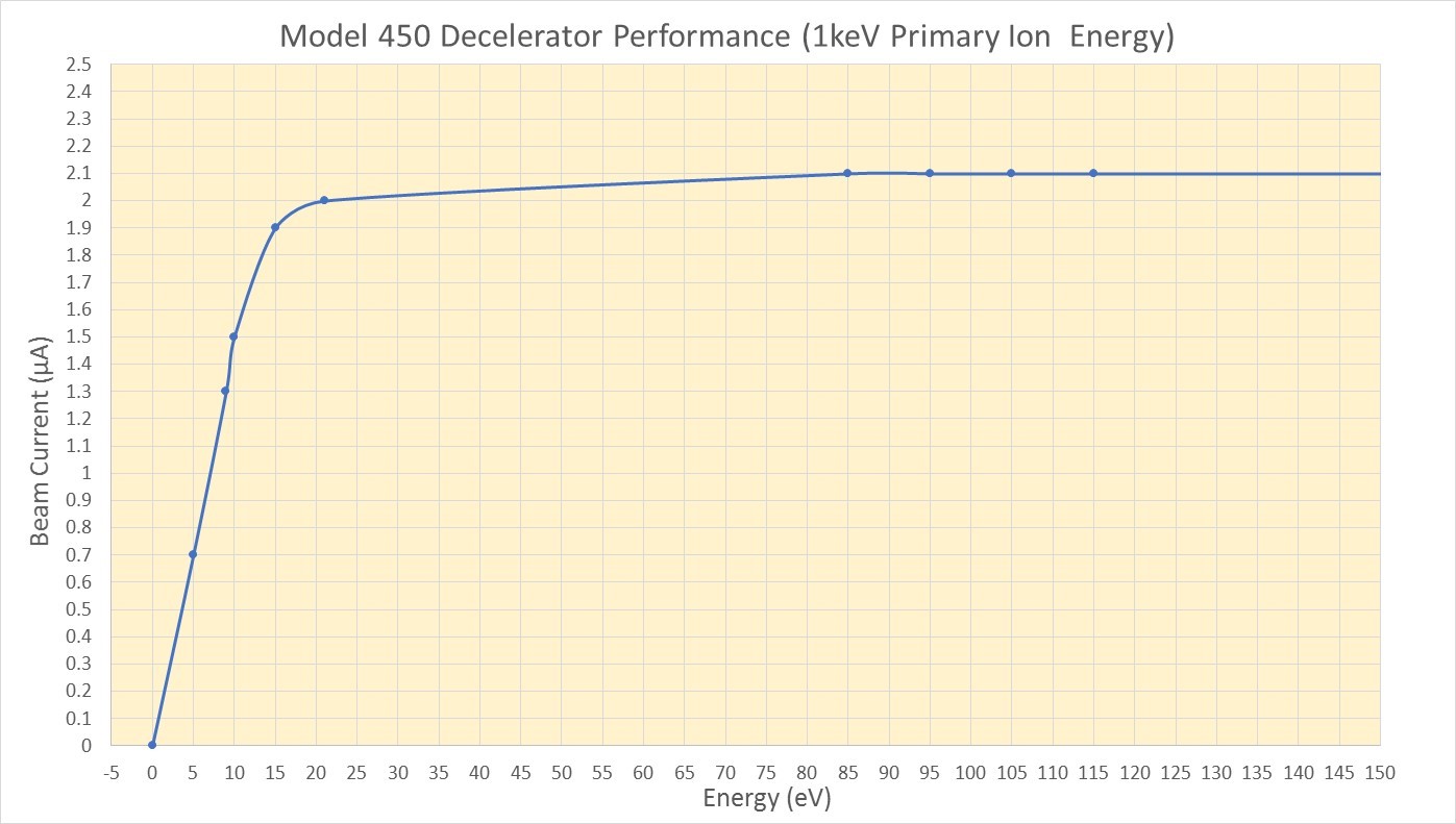
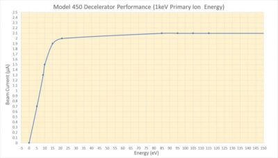
The performance curve above was generated by measuring the Ar+ beam current with a 10mm diameter collector approximately 2.5cm from the exit of the decelerator. The performance was measured up to 5keV initial Ar+ ion energy but the decelerator is designed to be used with beams up to 10keV. For these measurements, the decelerator was mounted 12″ (30cm) from the exit of a Beam Imaging Solutions model G-2 ion gun system with RFIS-100 ion source. The target/collector was floated to the ion beam retarding potential. Final ion beam energy was calculated by measuring the difference between the initial ion energy (accelerating potential) and retarding potential. In cases were the target must be kept at ground potential, the ion gun electrodes can be floated to a negative accelerating potential with maximum floating potential -1kV. The beam performance curve for a primary ion beam with 1keV is shown below.
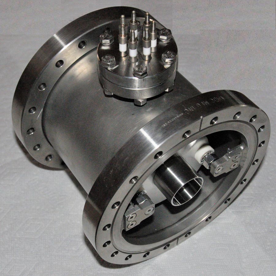
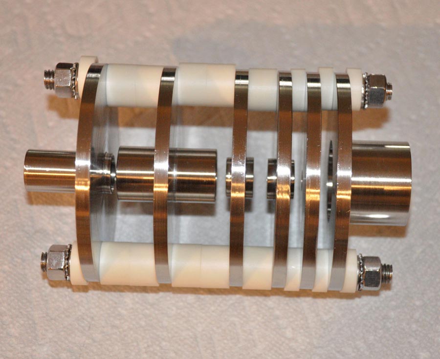
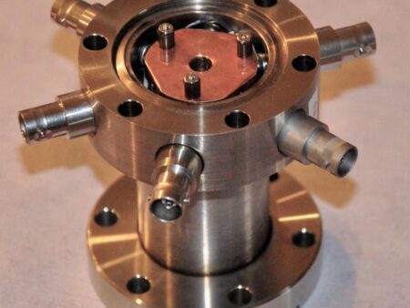
The decelerator is available with deceleration lens system (model 450-L) only or mounted in a vacuum chamber with electrical feedthroughs (model 450).
SIMION Geometery files and simulations are available upon request. Please see our contact page for contact information.
Model 400/450 Decelerator Operation Methods
There are two methods that can be used to operate the model 400/450 decelerators and they are discussed in detail below. They are based upon the availability of different types of power supplies. The advantages and disadvantages of both approaches are also discussed.
Method 1
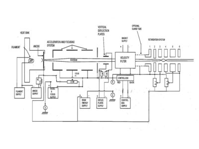
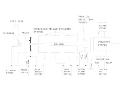
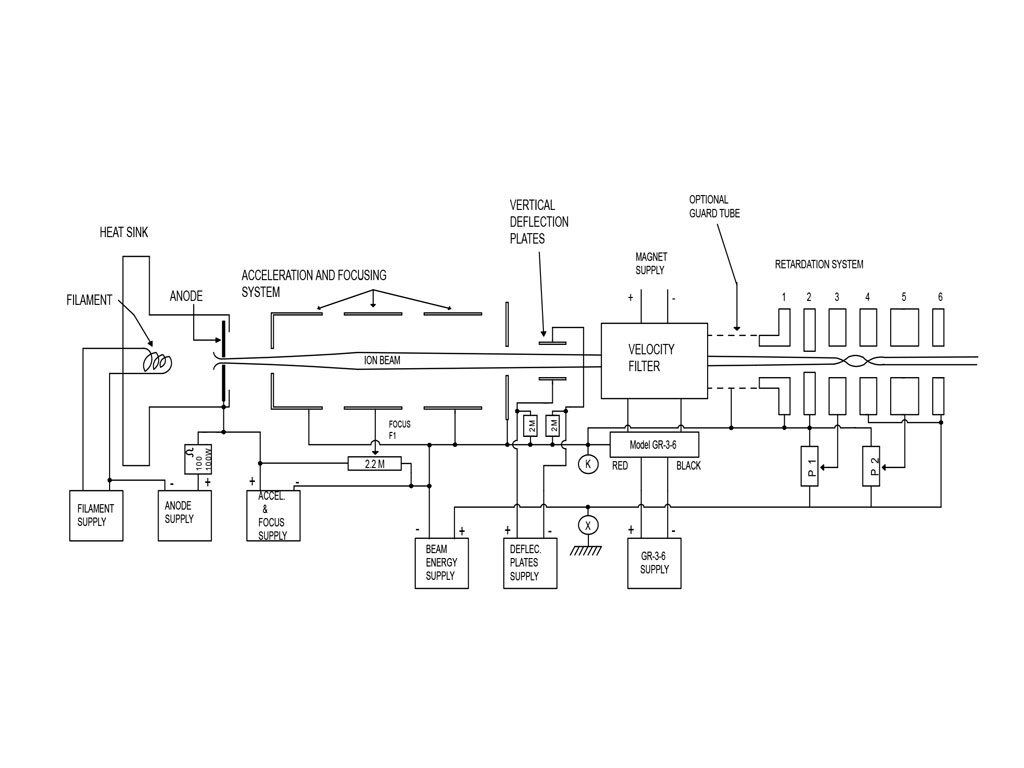
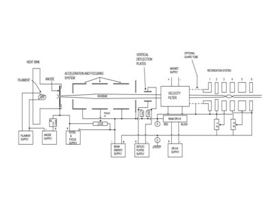
Method 1 uses a positive 1kV,10mA power supply for the Beam Energy Supply and a negative 1kV,10mA power supply for the Acceleration and Focus power Supply (A1). The K connection point which is normally grounded in the high energy mode configuration (See Addendum) is left floating and X connection is instrument ground. Using this method if the final ion beam energy is +10eV for example, then the Beam Energy Power Supply is set to +10V. The Acceleration and Focus Power Supply (A1) can be adjusted to -1kV for maximum extraction voltage. This will put the floating ground point K at -1kV with respect to instrument ground point X. The total ion beam extraction voltage in this case would be 1,010V. The pot F1 (500 kΩ, 2W) is used to focus the ion beam to the decelerator through the main lens system of the ion gun. As the beam approaches decelerator electrode #1, it will have an energy of 1,010 eV with respect to the floating ground, point K. By adjusting pot P1 (500 kΩ, 2 W) the beam is decelerated in two stages between lens elements #2 and #3, as well as between lens elements #3 and #4. After the beam passes through lens element #4, it will have been decelerated to 10eV with respect to instrument ground point X. After it passes through lens element 4 it will be divergent but can be focused to the target by lens element #5 which is the center lens element of an einzel lens configuration using pot P2 (500 kΩ, 2W). Once the ion beam leaves the last lens, especially at low energy, it will be susceptible to space charge expansion of the beam so it is advised to have the target relatively close to the exit of the decelerator. The pots F1, P1 and P2 are adjusted to give maximum current throughput to the target. The vertical deflection plates and velocity filter controls are also used to maximize the current through the decelerator.
IMPORTANT: Normally the decelerator is operated on the exit flange of the ion gun. If the decelerator must be operated far from the exit of the ion gun, a shield/guard tube should be installed between the gun exit and the decelerator and electrically connected to the floating ground, connection point K. (See circuit diagram).
Advantages (compared to Method 2): This method has the advantage that the acceleration/extraction potential of the ion beam can be greater than 1kV. For method 2 the extraction potential is constant for all beam final beam energies. Using method 1 for example, a 500eV beam will be have an extraction potential of 1500V and the greater the extraction potential, the greater the final ion beam current.
Disadvantages (compared to Method 2): When using method 1, every time the beam energy is changed, the ion beam focus voltage and velocity filter settings must be readjusted because the ion beam energy as the ion pass through the focus and velocity filter section of the ion gun will have changed. When using method 2 however, as the final ion energy is changed, the extraction potential is held constant so the ion beam energy of ions as they pass through the focus and velocity filter are unchanged.
Method 2 (preferred)
Method two uses a -1kV,10mA Beam Energy Power Supply and a 1kV,10mA Acceleration and Focus Power Supply (A1) with floating outputs. The floating outputs allow the power supply to float up to 1kV. In this method to achieve the maximum amount of extracted current for say a 10eV ion beam, the Beam Energy Power Supply would be set to -990V and the Acceleration and Focus Power Supply would be set to +1000V. Final Energy is determined by the Acceleration and Focus Power Supply plus beam Energy Power Supply, in this case 1000V + (-990V) = 10V. Again, in this method, connection point K is left floating and connection point X is electrically connected to the instrument ground. The negative terminal of the beam energy power supply is connected to the negative output of the floating power supply and connection point K. The positive output of the Acceleration and Focus Supply is connected to the ion source. Using this method, the total extraction potential is set by the Acceleration and focus supply which is +1000V maximum. The ion beam will approach decelerator lens element #1 with an energy of 1,000 eV. The pot F1 (500 kΩ, 2W) is used to focus the ion beam to the decelerator through the main lens system of the ion gun. Like method 1, the ion beam will be decelerated in two steps and focused by lens element #5 using pots P1 (500 kΩ, 2W) and P2 (500 kΩ, 2W).
Again, once the ion beam leaves the last lens, especially at low energy, it will be susceptible to space charge expansion of the beam so it is advised to have the target relatively close to the exit of the decelerator. The pots F1, P1 and P2 are adjusted to give maximum current throughput to the target. The vertical deflection plates and velocity filter controls are also used to maximize the current through the decelerator.
IMPORTANT: Normally the decelerator is operated on the exit flange of the ion gun. If the decelerator must be operated far from the exit of the ion gun, a shield/guard tube should be installed between the gun exit and the decelerator and grounded to the floating ground, connection point K. (See circuit diagram).
Advantages (compared to Method 1): This method has the advantage that the initial acceleration/extraction potential of the ion beam can be set at 1kV for all final ion beam energies. This means that the focus and velocity filter tuning would not need to be re-adjusted if the final ion beam energy is changed.
Disadvantages (compared to Method 1): Method 1 will have slightly higher final beam currents than method 2 since the extraction potential can be made slightly greater than method 2.
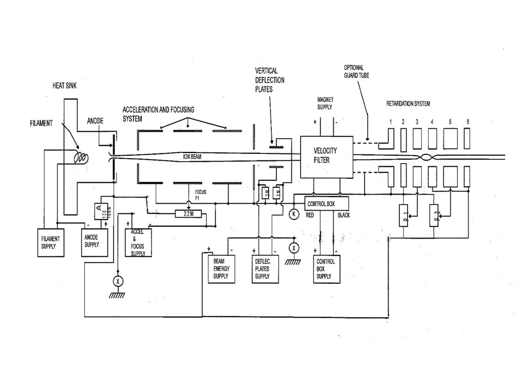
Addendum
High Energy Mode Circuit Diagram (Energies >1keV when decelerator is not used). Connection point K is instrument ground.