High Resolution Beam Imaging is made possible with the Beam Imaging Solutions HRBIS systems. The HRBIS can be used to measure two or three dimensional intensity distributions of ion, electron and neutral beams. The HRBIS can also be used to image X-rays for applications such as pinhole imaging and spectroscopy.
High Resolution Beam Imaging is made possible with the Beam Imaging Solutions HRBIS systems. The HRBIS can be used to measure two or three dimensional intensity distributions of ion, electron and neutral beams. The HRBIS can also be used to image X-rays for applications such as pinhole imaging and spectroscopy.
Images are created using a micro-channel plate (MCP) and phosphor screen combination. The phosphor is uniformly deposited onto a coherent fiber-optic (FO) substrate so that the image can be optically transmitted to the outside of a vacuum system for analysis. The image is coherently transmitted using a series of FO conduits to a vacuum viewport at which the image can be viewed by eye or recorded and processed with CID or CCD camera systems. The HRBIS systems are available in many different configurations to best fit a customer’s particular application and budget.
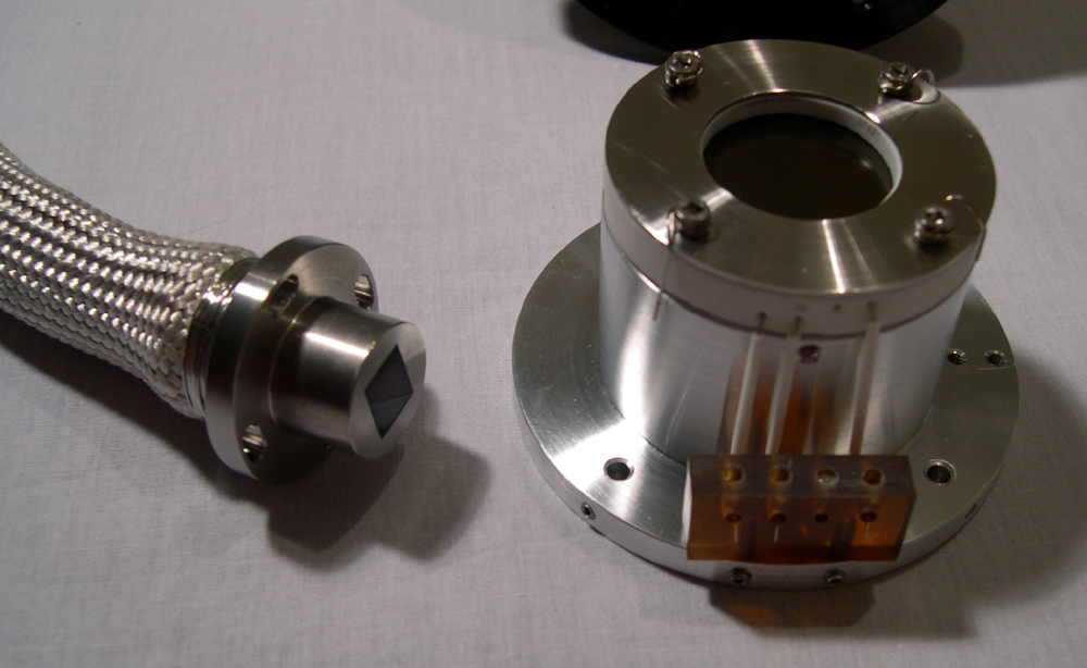
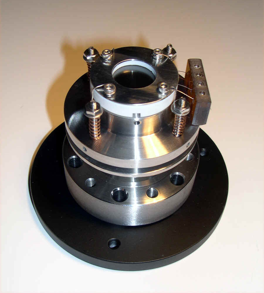
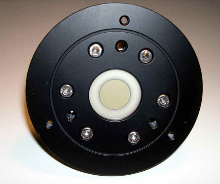
The Model HRBIS-11000 High Resolution Beam Imaging System is shown below. The image on the right shows the camera adapter ring that is standard with the HRBIS. The ring has threaded holes for attaching a camera mounting system, available with all of the optional camera systems.
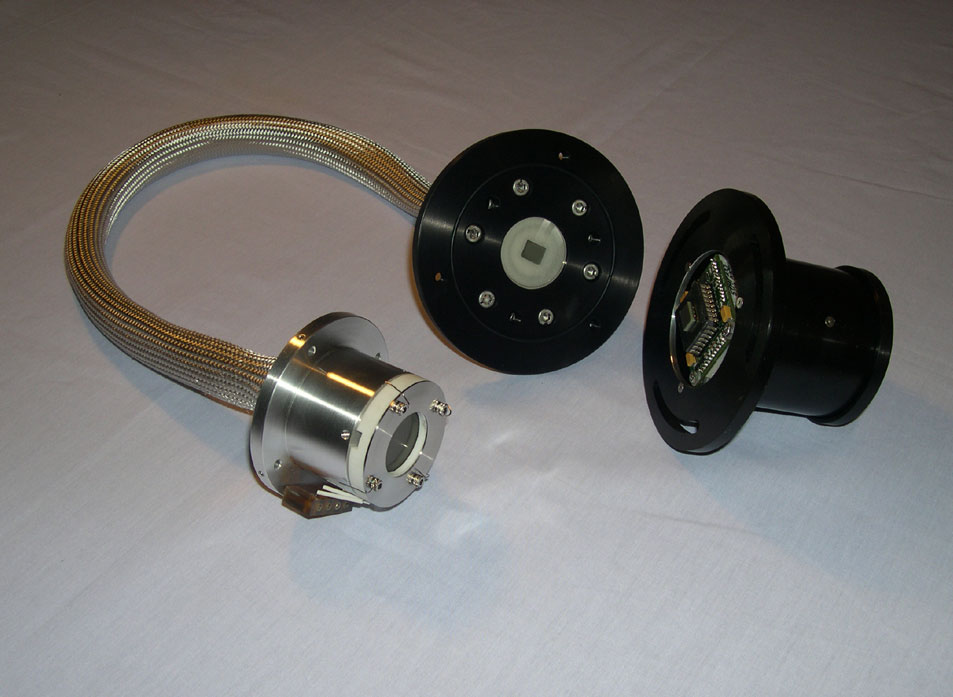
HRBIS-20034 with Flexible Fiberoptic Cable coupling (Remote System)
HRBIS-41024 with Fiberoptic Rod coupling (Standard System)
The Model HRBIS-11000 High Resolution Beam Imaging System is shown below. The image on the right shows the camera adapter ring that is standard with the HRBIS. The ring has threaded holes for attaching a camera mounting system, available with all of the optional camera systems.
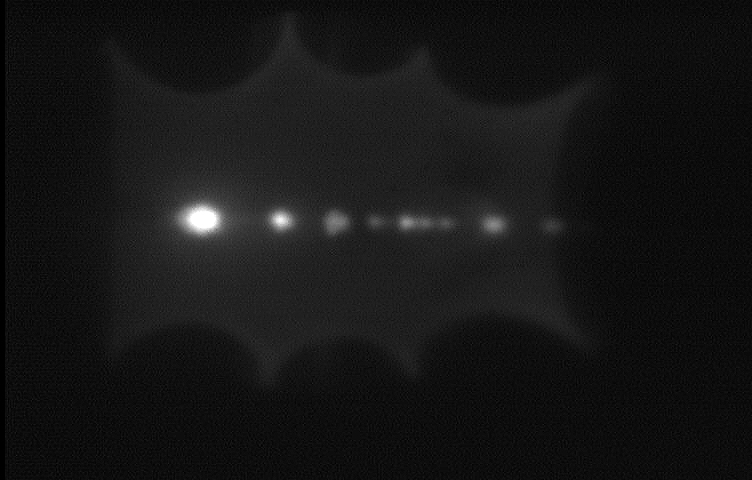
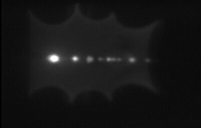
Mass separated ion beam showing fringe fields of E X B Wien filter. Image was made with model HRBIS-40034 imaging system and model IPS-1 image process system. Image is ~36.4mm x 26.4mm
Technical Information
System Configuration
The probe heads, fiberoptic conduits and camera systems shown below are all interchangeable. The systems can be custom configured to meet your particular system requirements by specifying the appropriate HRBIS model number (see the table above).
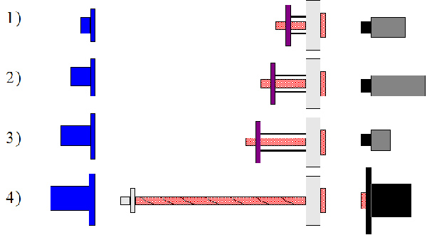
Probe Heads Coherent Fiber-Optic Conduits Camera System (with 2.75″ Conflat®, Fiber-Optic Viewport) (with camera mount systems)
1) HRBIS-1-PH     1) Solid Fiber-Optic   Rod (L=2", D=0.75")  1) COHU 2600, Lens
2) HRBIS-2-PH     2) Solid Fiber-Optic   Rod (L=3", D=0.75")  2) COHU 2700, Lens
3) HRBIS-3-PH     3) Solid Fiber-Optic   Rod (L=4", D=0.75")  3) CIDTEC 3710D, Lens
4) HRBIS-4-PH     4) Flexible   Fiber-optic bundle, (60 cm)   4) CIDTEC 3710D, FO FP
                  CR Custom Rod Length                        5) Sony XCD-U100, FO FP
                  CC Custom Cable Length                      6) Sony XCG-SX97E,FO FP
                                                              7) Custom,Customer Spec.
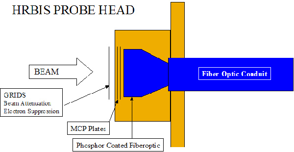
The HRBIS systems consist of three basic components:
1) the HRBIS probe head which houses the MCP and phosphor screen;
2) a fiber-optic conduit which optically transmits the image from the probe head to a fiber-optic vacuum feedthrough; and,
3) a camera system for digital readout of the image. These components are described in detail below.
Probe Head
Probe Head Specifications
Probe Head Model Number
Image Area
Approximate Spatial Resolution
HRBIS-1-PH
17mm diam.
25-35µm
HRBIS-2-PH
25.4mm diam.
50-70µm
HRBIS-3-PH
38.4mm diam.
75-100µm
HRBIS-4-PH
~ 44.45mm diam.
150µm
Probe Head – Optional Configurations
Probe heads are available with a single MCP (standard) or dual MCP (chevron) configuration for increased gain. MCP’s are imaging grade and are available with optional coatings on the MCP input face. Coatings include CsI, CuI, MgF2, MgO, KBr, Cu, and Au.
The phosphor screens come standard with P-43 phosphor and conductive aluminum over coating. Other phosphors are available upon special request, as well as an Indium-Tin-Oxide (ITO) under coating. ITO screens are generally used when lower electron accelerating voltages are required, however the quantum yield may be lower than that of aluminized screens.
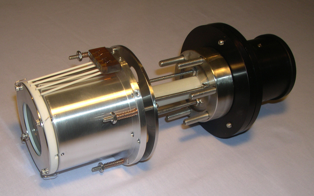
The probe heads also have the capability of mounting a variety of apertures, slits, lenses, pinholes, filters and grids using 1/8″ (3mm) diameter ceramic mounting rods. Beam Imaging Solutions offers a small selection of grids that can be mounted in front of the probe head for applications such as electron suppression, beam attenuation, and beam acceleration. A 4-terminal high voltage feedthrough on 2 3/4″ (DN35) conflat® flange is provided with the HRBIS system for the phosphor screen and MCP voltage application.
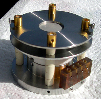
HRBIS-10000 probe head with two optional 90% beam attenuation grids. Grids are an electroformed Nickel mesh; in this case providing a total 99% beam intensity reduction. The use of these grids can help to prolong MCP lifetime for higher current ion beams.
Fiber-Optic Conduits
Images are transmitted optically from the probe head through one of two types of FO conduits to a 2 3/4″ (DN35) conflat® FO vacuum viewport. The image can then to be recorded on the outside of the vacuum chamber with a CCD/CID camera (see CCD and CID camera options below).
Conduits consist of either a flexible 60cm long, 10mm x 8mm rectangular FO cable (Remote Systems) or 19mm diameter solid FO rod (Standard Systems) which are available in various lengths. Both conduit types attach at one end to the HRBIS probe head, and to the FO viewport at the other end. The remote systems with flexible FO cable are especially useful for imaging particle beams deep within the vacuum chamber where the beam cannot be brought to a vacuum port for imaging.
The 60cm length is standard, however other lengths are available on request. The standard systems with solid FO rod are generally used when the beam can be brought close to a vacuum port for imaging.
The FO rod is available in various lengths to allow for greater flexibility when adapting to a customer’s particular application.
CCD and CID Camera Options
Optional CCD and CID camera readout systems are available for all HRBIS systems. All cameras are available with lens, video monitor and mounting system for imaging the FO viewport. The CIDTEC 3710D is also available with Fiber-Optic Face Plate (FOFP) directly attached to the camera sensor. The camera sensor is then mounted in a special housing which allows them to directly mate to the FO viewport. This direct FO coupling approach ensures highest possible resolution and gain. Cameras can be connected to a video monitor in order to observe images in real time, and can also be connected to a video frame grabber making it possible to store and analyze the images later. Beam Imaging Solutions offers optional Image Processing Systems (IPS) which include video monitor, frame grabber, cables and software. Beam Imaging Solutions is now offering the Sony XCD-U100 ( IEEE1394.b) and the Sony XCG-SX97E (GIGE) cameras with fiberoptic faceplates. Please contact Beam Imaging Solutions for more information.
CCD/CID Camera Specifications
Camera
CIDTEC 3710D
COHU 2722 (Dual Gain)
COHU 2622
Optical Format
2/3″ diagonal
1/2″ diagonal
1/2″ diagonal
Resolution
755H x 484V RS-170
752 x 582 CCIR
755H x 488V RS-170
752 x 582 CCIR
768H x 494V RS-170
752 x 582 CCIR
Element Pitch (micron)
12.0 x 13.7
8.4 x 9.8
8.4 x 9.8
Area (mm)
9.05 x 6.83
6.4 x 4.8
6.4 x 4.8
FOFP (Optional)
4.5 micron pitch
N/A
N/A
Scanning Format
RS-170, 2:1 Interlace
EIA RS-170, CCIR
EIA RS-170, CCIR
Electronic Shutter
1/60 to 1/100,000
1/60 to 1/10,000
Sync. System
Int./Ext.
Int./Ext.
Int./Ext.
Signal to Noise (db)
50
58 max.
>55
Sensitivity (Face Plate Illumination)
Full Output: 0.5fc
Full Output: 0.0012 lux
Full Output: 0.5fc
Input Power (Watts)
8.5 max.
6 max.
3.6
Input Voltage (Volts)
+15VDC nominal
+24VDC or 115VAC
+12VDC
Dimensions
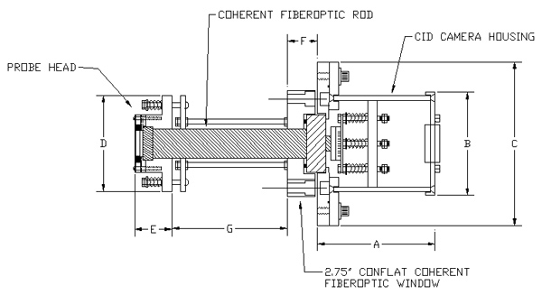
HRBIS Standard Systems (Fiberoptic Rod Conduit)
Dimensions (Shown with optional CIDTEC 3710D camera)
MODELS*
HRBIS-1XX04
HRBIS-1XX14
HRBIS-1XX24
HRBIS-2XX04
HRBIS-2XX14
HRBIS-2XX24
DIM
(mm)
A
77.5
77.5
77.5
77.5
77.5
77.5
B
68.3
68.3
68.3
68.3
68.3
68.3
C
108.0
108.0
108.0
108.0
108.0
108.0
D
63.5
63.5
63.5
76.2
76.2
76.2
E
24.4
24.4
24.4
43.3
43.3
43.
F
20.0
20.0
20.0
20.0
20.0
20.0
G
25.4
50.8
76.2
25.4
50.8
76.2
Fiber-optic Rod O.D.
19.1
19.1
19.1
19.1
19.1
19.1
MODELS*
HRBIS-3XX04
HRBIS-3XX14
HRBIS-3XX24
HRBIS-4XX04
HRBIS-4XX14
HRBIS-4XX24
DIM
(mm)
A
77.5
77.5
77.5
77.5
77.5
77.5
B
68.3
68.3
68.3
68.3
68.3
68.3
C
108.0
108.0
108.0
108.0
108.0
108.0
D
88.9
88.9
88.9
101.5
101.5
101.5
E
56.3
56.3
56.3
70.09
70.09
70.09
F
20.0
20.0
20.0
20.0
20.0
20.0
G
25.4
50.8
76.2
25.4
50.8
76.2
Fiber-optic Rod O.D.
19.1
19.1
19.1
19.1
19.1
19.1
* The model number X descriptor determines the MCP and phosphor screen options (See ordering Information Table at top of Web Page).
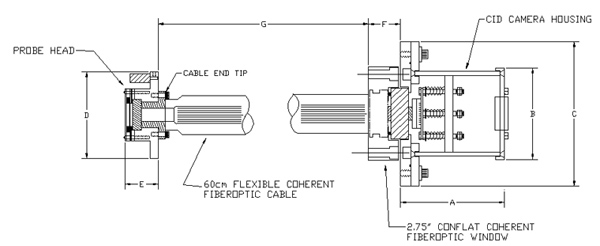
HRBIS Remote Systems (Flexible Fiberoptic Cable)
Dimensions
MODELS*
HRBIS-1XX34
HRBIS-2XX34
HRBIS-3XX34
HRBIS-4XX34
DIM
(mm)
A
77.5
77.5
77.5
77.5
B
68.3
68.3
68.3
68.3
C
108.0
108.0
108.0
108.0
D
63.5
76.2
88.9
101.5
E
24.8
43.3
56.3
70.09
F
23.9
23.9
23.9
23.9
G
566.7
566.7
566.7
566.7
CABLE END TIP O.D.
34.3
34.3
34.3
34.3
* The model number X descriptor determines the MCP and phosphor screen options (See ordering Information Table at top of Web Page).
Schematics
HRBIS-10000 probe head with two optional 90% beam attenuation grids. Grids are an electroformed Nickel mesh; in this case providing a total 99% beam intensity reduction. The use of these grids can help to prolong MCP lifetime for higher current ion beams.