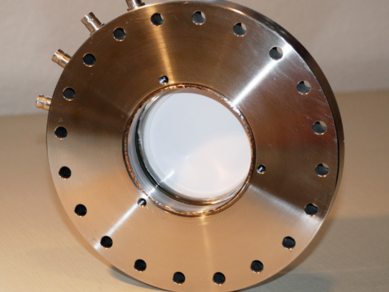
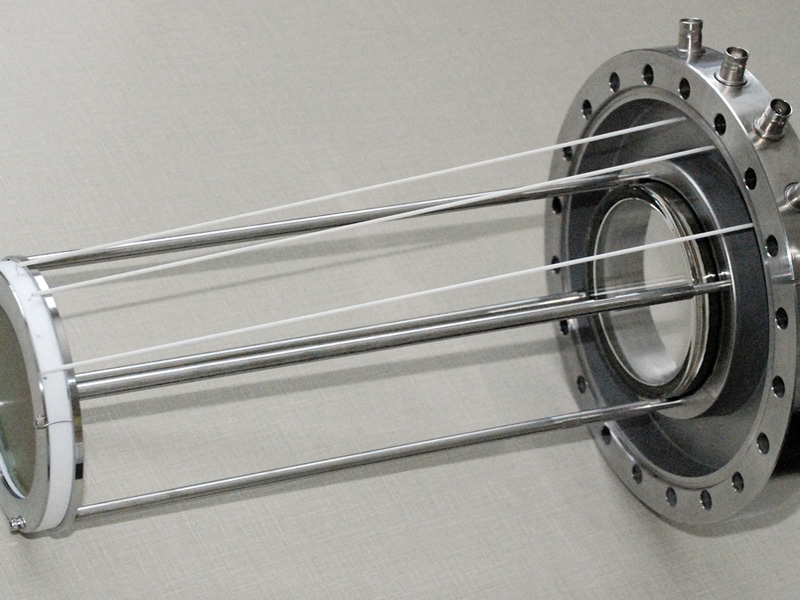
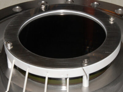
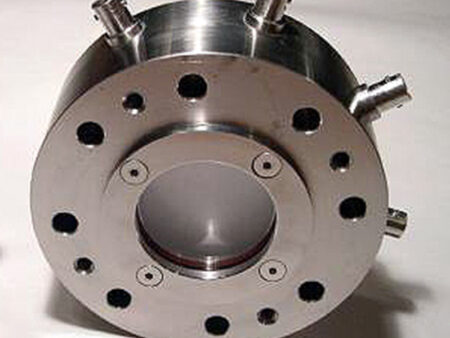
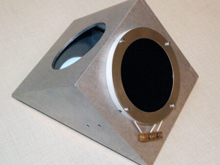
In standard form, the model BOS-75 Beam Observation system has a 75mm diameter active area MCP and P-43 phosphor screen assembly, attached to a 8.00″ (203mm) conflat flange with glass viewport. Electrical connections to the phosphor screen and MCP are made with MHV feedthroughs.
In standard form, the model BOS-75 Beam Observation system has a 75mm diameter active area MCP and P-43 phosphor screen assembly, attached to a 8.00″ (203mm) conflat flange with glass viewport. Electrical connections to the phosphor screen and MCP are made with MHV feedthroughs.
Optional configurations are discussed in detail in these product tabs and include, dual MCP plates (chevron), SHV feedthroughs, and CCD camera systems.
Technical Information
Imaging Area
75mm Diameter
MCP (Standard)
3.410″ Diam. (BOS-75), 25 micron channel diameter, Detection or Imaging Grade, 75mm active area, 32 micron pitch, 8° Bias Angle, 40:1 Aspect Ratio (Standard, BOS-75), Min. Gain: 1 x 10^4 (single plate, Std.) 1000V > 107 (chevron, OPT-01), 2000V
Phosphor Screen (Standard)
P-43 with aluminum overcoat. P-43 Peak Wavelength: λ= 545 nm.
1 x 10⁻⁶ Torr or better required to operate MCP, UHV compatible, maximum bakeout temperature 300 C
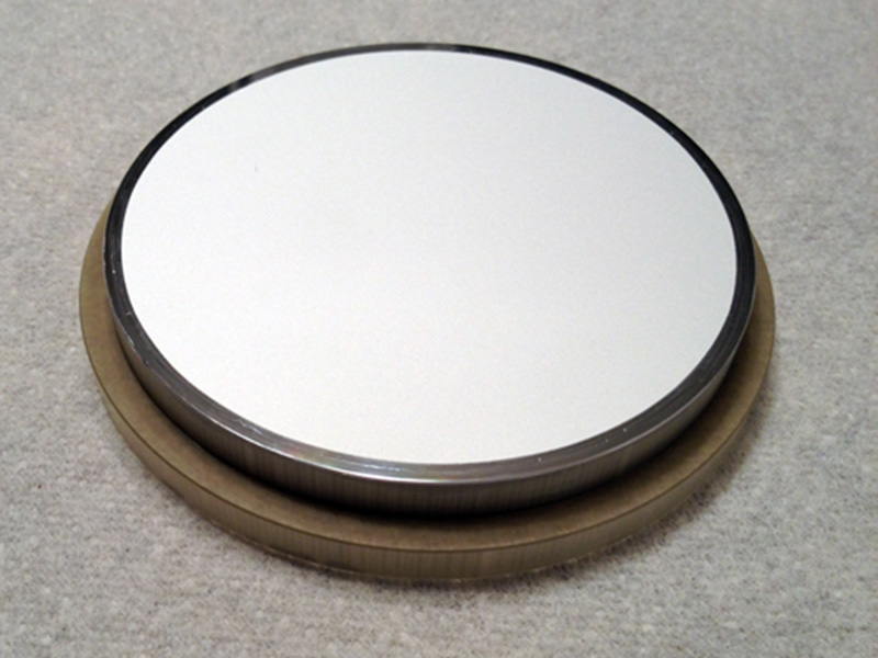
Welded Glass Windows (Standard)
A non-removable glass window that is welded to the flange is standard. This allows bakeout temperatures > 200C.
Product Schematics
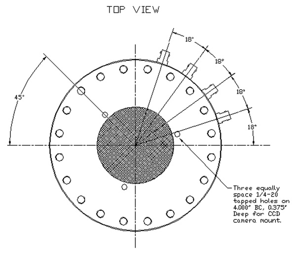
BOS-75 (Top View)
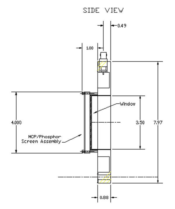
BOS-75 (Side View)
Optional Equipment
Dual MCP systems, MCP Coatings and MCP Type:
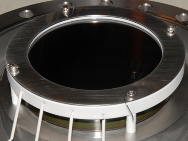
Model BOS-75 with BOS-75-OPT-01 dual MCP option
MCPs with optional coating for enhanced imaging of UV and X-rays (KBr, CsI, Cu, CuI, MgO, Au,MgF2)
MCPs with high gain and resolution
MCPs with matched characteristic impedance
Phosphor Screen
P-43 is standard but other phosphors are available and include including P1, P11, P15, P20, P22, P24, P31, P45, P46, P47, P48, and P53. See our phosphor screen page for more information. Screens have a standard aluminum overcoat but Indium-Tin-Oxide (ITO) undercoating is also available.
Stand alone MCP/Phosphor assemblies (IDA) (Optional)
The MCP/Phosphor screen assemblies used by the BOS-75 are available separately.
BOS-75-CH-IDA (75mm Dual MCP with P-43 Phosphor Screen)
Coherent Fiberoptic Windows (Optional)
Using a fiberoptic faceplate for the vacuum window is the optical equivalent of a zero thickness window. Phosphor is coated on the vacuum side surface of the fiberoptic window. The image created at the surface of the phosphor is transmitted through the optical fibers of the window to the front surface (air side) of the window by for easy viewing of the image by eye or mountable camera systems. This design allows the phosphor screen to be removed and re-coated or replaced with a different kind of phosphor, without having to remove the MCP assembly.
Fiberoptic Window/Phosphor Screen (PN-75-FO)
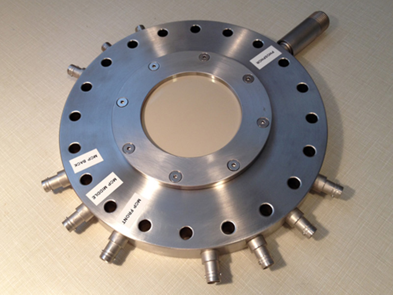
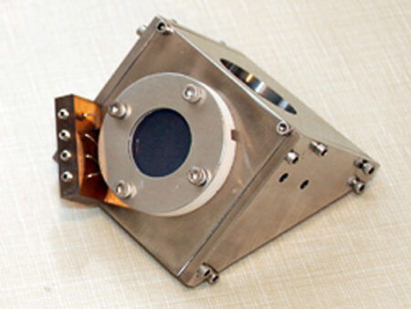
BOS-75-FO With Optional Extra Feedthroughs
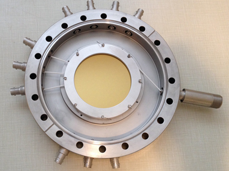
BOS-75-FO With Optional Extra Feedthroughs (Vacuum Side)
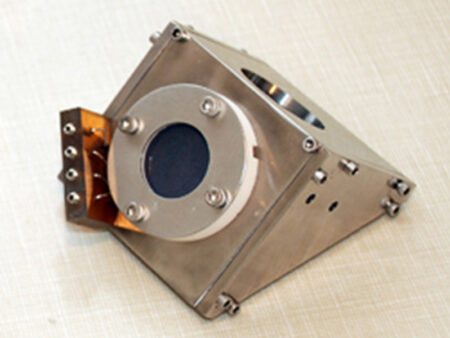
Extended Platform Mounts (Optional)
The MCP/Phosphor screen assemblies can be mounted on an extended platform at a specific distance from the vacuum sealing surface or BOS window. This distance is specified by the customer.w
Image Processing Systems (Optional)
Model IPS-1 (Frame grabber (PCI bus), cables, software)
Power Supplies (Optional)
Model MCPPS-1 (MCP Power Supply, Single MCP, 0-1kV)
Model MCPPS-2 (MCP Power Supply, Dual MCP, 0-2kV)
Model PHSPS-1 (Phosphor Screen Power Supply, 0-5kV)
Miscellaneous Options
SHV, SHV-B, BNC Feedthroughs, Electron suppression grids
Beam attenuation grids (90%, 99%, 99.9%)
Please use these criteria when determining number of attenuation grids needed:
Ion beams greater than 3.2 nA/mm2, 90% beam attenuation (1 grid)
Ion beams greater than 31.8 nA/mm2, 99% beam attenuation (2 grids)
Ion beams greater than 318.nA/mm2, 99.9% beam attenuation (3 grids)
BOS Camera Options and Specifications
*All camera systems include lens, BOS mounting hardware, video cable, and 12″ high-resolution monochrome monitor*