Product Overview
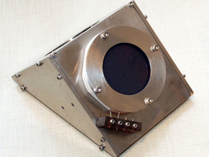
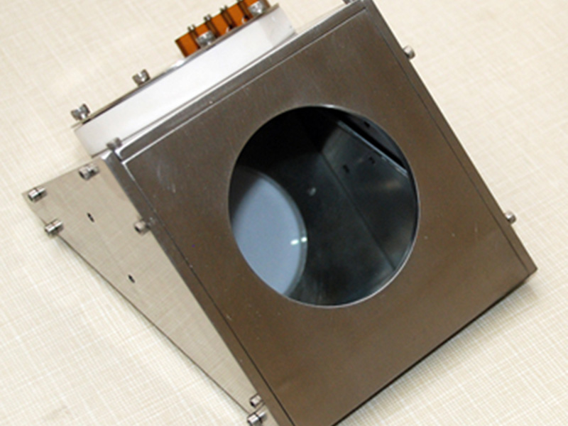
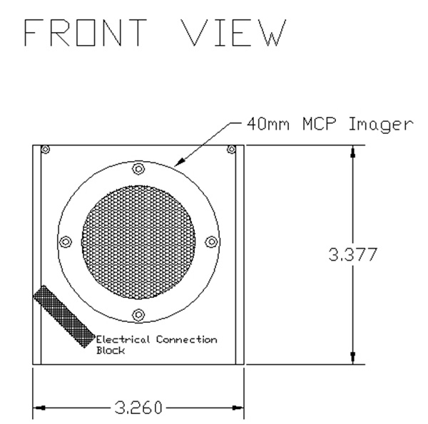
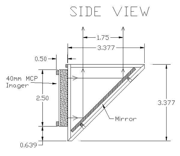
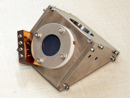
Beam Imaging Solutions (BIS) introduces the 90-degree BOS which allows remote imaging of a beam at 90 degrees to the imaging plane. The BOS-40-IW can be attached to a linear motion feedthrough and placed into and out of the beam allowing for remote imaging, deep within the vacuum chamber. The imaging is accomplished by mounting a standard BOS MCP/phosphor screen stack onto a metal housing which has a mirror mounted at 90-degrees with respect to the imaging plane. The housing is wedged shaped to minimize the physical size of the imager, and has convenient points for attaching to a linear motion feedthrough. Electrical connections are made by attaching flexible electrically insulated wires to a connection block on the wedge from an electrical feedthrough. In their standard form, the BOS-IW units are available with the MCP/phosphor assembly mounted to wedge shaped housing with electrical connection block. BOS-IW kits are also available, and include the BOS-IW unit with electrical feedthrough, viewport, linear motion feedthrough and camera systems. Contact us for more details.
Optional Equipment
Dual MCP systems, MCP Coatings and MCP Type:
- Model BOS-40-IW with BOS-40-IW-OPT-01 dual MCP option
- MCPs with optional coating for enhanced imaging of UV and X-rays (KBr, CsI, Cu, CuI, MgO, Au,MgF2)
- MCPs with high gain and resolution
- MCPs with matched characteristic impedance
Phosphor Screen
P-43 is standard but other phosphors are available and include including P1, P11, P15, P20, P22, P24, P31, P45, P46, P47, P48, and P53. See our phosphor screen page for more information. Screens have a standard aluminum overcoat but Indium-Tin-Oxide (ITO) undercoating is also available.
Image Processing Systems (Optional)
- Model IPS-1 (Frame grabber (PCI bus), cables, software)
Power Supplies (Optional)
- Model MCPPS-1 (MCP Power Supply, Single MCP, 0-1kV)
- Model MCPPS-2 (MCP Power Supply, Dual MCP, 0-2kV)
- Model PHSPS-1 (Phosphor Screen Power Supply, 0-5kV)
Miscellaneous Options
- Beam attenuation grids (90%, 99%, 99.9%)
- Please use these criteria when determining number of attenuation grids needed:
- Ion beams greater than 3.2 nA/mm2, 90% beam attenuation (1 grid)
- Ion beams greater than 31.8 nA/mm2, 99% beam attenuation (2 grids)
- Ion beams greater than 318.nA/mm2, 99.9% beam attenuation (3 grids)
- Electron suppression grids

